Many people have the impression of OpenFOAM being difficult and complex. And several mind boggling boundary conditions are one of the reasons. If you are still not very familiar with OpenFOAM file structure, you may want to read our tutorial about the file structure here.
In this article, we will categorize and explain some of the most used boundary conditions for incompressible fluid flows. If you grasp the idea of boundary conditions and patch types, you will be able to expand your understanding to any other phenomena such as compressible flows, heat transfer, moving meshes, solid mechanics, etc. Of course, your understanding of the underlying phenomena you want to compute in OpenFOAM is assumed!
Before going directly to the files in you 0/ directory for actual settings, let’s have a look at the patch types for your boundary patches.
So, what is a patch?
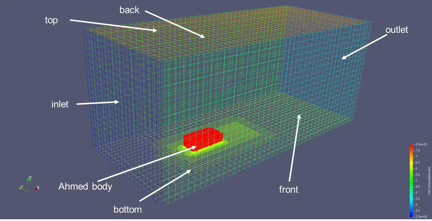
What does the word “patch” even mean? In OpenFOAM, a patch is a boundary surface in a mesh at which various boundary conditions can be applied. Above image is the boundary patches of my Ahmed body simulation visualized in Paraview. The important patches in this simulation are inlet, outlet and ahmed body patches. So, a patch may either be a flat surface or any arbitrary shape like the Ahmed body patch. Boundary conditions are applied at the faces of these patches.
And the following is part of the boundary file representing the above patches. This boundary file is located inside the constant/polyMesh directory and it is the most important file among the mesh files because you can change the patch names and types here to match your boundary conditions.
You can see we have patch name, patch type, nFaces and startFace. nFaces is the number of faces that make up the patch and startFace is the starting face number of the patch.
But our main interest is the patch type.
The patch name is the name of the patch we want to focus. This name must be the same for all of your boundary and initial condition files inside 0/ directory. For example, the name “inlet” is used in 0/U and 0/p files to define the velocity and pressure boundary conditions for the patch “inlet”. In other words, the names inside the boundary file must be the same as those across all files in 0/ directory. Otherwise, you will face the dreadful “FOAM FATAL ERROR” message when running your solver.
So, we have two main base types. Patch and wall. If flow or flux is passing through the surface, we can use patch type. If the flow velocity is zero at the patch, causing a boundary layer, we should use wall. There are other patch types for several different conditions.
So, we now know that we need to match the patch names for boundary file and files in 0/. Again, we also need to match the patch type and boundary condition type. For example, in the above images, for inlet patch, we want to assign a uniform velocity inlet. Thus, we defined a fixedValue boundary condition for inlet in 0/U file and give it a uniform velocity of (5 0 0) m/s. For the pressure boundary condition, we want the solver to figure out the pressure at the inlet patch from its nearest cells. Thus, we gave a zeroGradient condition.
Patch type and boundary conditions
But what boundary conditions are available for different patch types? What are available for patch types and what are available for walls and what are available for others like empty and symmetry types?
The following graph shows the velocity and pressure boundary conditions available for your patches and walls. Although these are available for use, your understanding of underlying flow physics is the most important when choosing the boundary condition type for your patch or for your wall.
On the other hand, several base type boundary conditions are simple to use. If you define symmetry boundary condition for a patch, you just assign symmetry for both 0/U and 0/p files. The same goes for the third row of the given graph.
So, the brief explanation of some of these boundary conditions are as follows.
fixedValue: This is the classical Dirichlet boundary condition which means a fixed value is applied to the flow variables. For example, fluid touching a stable wall has zero velocity. You can then set uniform (0 0 0) for the velocity boundary condition of that wall.
zeroGradient: This is the Neumann boundary condition and it means your normal gradient at the patch is zero. Again, it means your flow variable of interest at the patch is an arbitrary constant. Therefore, if you do not know a flow variable at a patch, you may use zeroGradient. For example, you assign zeroGradient for pressure at the velocity inlet because you know pressure is a constant and the solver will compute it for you. However, although for wall boundaries, zeroGradient for pressure is a go-to approach, there has been a lot of debate about what it even means. I would not touch these details.
movingWallVelocity: If your wall is moving, the effect of that motion to the flow field must be taken into account. movingWallVelocity boundary condition can handle this by imposing the velocity of the wall to the wall patch itself.
symmetry: This assign the patch as a symmetry plane. You can use this for farfield boundaries or if you want to compute only the half of your domain. There is another boundary condition symmetryPlane but it is much more restrictive because all your face normals must align. If you are using snappyHexMesh to generate your mesh, symmetry is the way to go. Your mesh is not good enough for symmetryPlane, I can guarantee.
empty: This is for defining 2D simulations. OpenFOAM is fundamentally a 3D CFD code. If you make your simulation 2D, just have one layer of cells and make the faces empty. You can use the famous cavity tutorial as an example.
cyclic: This special boundary condition can be used for periodic boundary conditions. Again, the faces you are coupling must have same topology and same node points because one-on-one mapping is done between the patches.
Boundary conditions for external incompressible aerodynamics
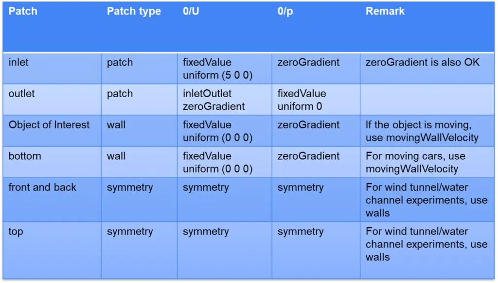
Well, you may think “So, what are the boundary conditions for your Ahmed body case?”. Here is the list of boundary conditions. You can use these for other incompressible external flow problems such as flow around airfoils, flow around a cylinder, flow around a Tesla cyber truck, etc.

Inlet: For velocity inlets, fixedValue is the most fundamental boundary condition. You can also use mass flow rate or volume flow rate conditions by choosing flowRateInletVelocity boundary condition if you have data for flow rate rather than velocity itself. Since pressure will be computed from the solver, zeroGradient is our go-to condition for 0/p.
Outlet: Outlets are mostly pressure outlets where you define the pressure at outlet to be zero. Therefore, for the pressure 0/p, we can set to fixedValue and give it a uniform 0 value. For velocity, we will not pose any fixed values because it will violate the continuity equation and blow up the solver. So, zeroGradient is a nice start for most of the situations. If backflow/reverse flow is expected, inletOutlet condition with possible inlet properties should be used. inletOutlet boundary condition is basically a zeroGradient with a special treatment for reverse flows.
Object of Interest: This is our main object we want to test via our CFD simulation. It is basically a non-slip wall. Thus, use fixedValue and give a zero velocity or just use nonSlip condition. If the object is moving such as flow around oscillating cylinders or flapping wings, movingWallVelocity boundary condition MUST be used. Otherwise, your results will be physically incorrect.
Bottom: If the bottom is a stationary wall such as when you are carrying out CFD for your wind tunnel test, you should use a non-slip stationary wall. But if you are doing a car moving in real-world scenario, you have to include the motion of ground surface. So, give a moving wall velocity with a constant velocity. If your bottom is far field, you can use symmetry.
Front and Back and Top: If these boundary are far field boundaries away from your body, you can use symmetry. If these boundaries are physical walls and have significant effects on your flow field, you need to set as walls.
Where to look for the details?
OK, I explained some of the most used boundary conditions. But there are several other base and derived boundary conditions in OpenFOAM designed to imitate several complex and complicated physical phenomena. Everything is not just fixedValue and zeroGradients. It is true, and you need to dig up the OpenFOAM source code for all the details. These files are located in $FOAM_SRC/finiteVolume/fields/fvPatchFields/derived. You can go inside your interested boundary condition and read the header file. The major description of the boundary condition and an example is almost always given in this header file.
Or you can consult with the doxygen documentation if you generated it during OpenFOAM compilation or on the internet.
Summary
constant/polyMesh/boundary file is a very important file for boundary conditions.
Your understanding of physical phenomena is utmost important when defining boundary conditions.
You can look up at the source code if you are not still sure about the boundary conditions yet.


